
SODIMAS Ascenseur
France
Return to elevatorbob's Electric Elevators
Return to elevatorbob's Elevator Pictures
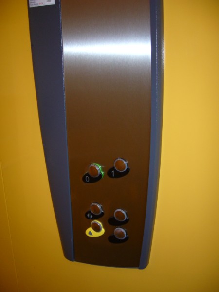
Image 1 ![]()
Car station...nice design!
Image provided by: Jonathan Fitzpatrick
Ascenseurs et Automatismes de Gascognes
I know more!
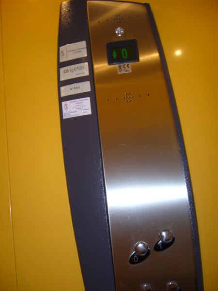
Image 2 ![]()
Car station...
Image provided by: Jonathan Fitzpatrick
Ascenseurs et Automatismes de Gascognes
I know more!
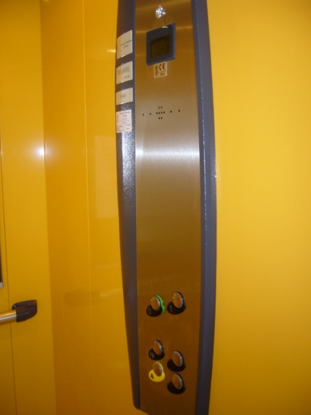
Image 3 ![]()
Car station...
Image provided by: Jonathan Fitzpatrick
Ascenseurs et Automatismes de Gascognes
I know more!
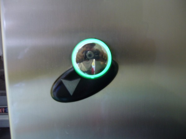
Image 4 ![]()
Corridor button...close-up
Is that Jonathan in the button?
Image provided by: Jonathan Fitzpatrick
Ascenseurs et Automatismes de Gascognes
I know more!
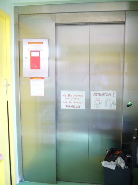
Image 5 ![]()
The red box is used to store the hoistway door unlocking tool and if you look
closely at the larger image you can see the access hole in the door jamb header.
Image provided by: Jonathan Fitzpatrick
Ascenseurs et Automatismes de Gascognes
I know more!
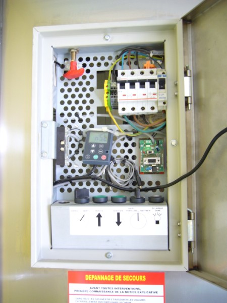
Image 6 ![]()
The maintenance/rescue panel located behind the red access tool box.
The red handle is used to manually release the machine brake if needed.
Image provided by: Jonathan Fitzpatrick
Ascenseurs et Automatismes de Gascognes
I know more!
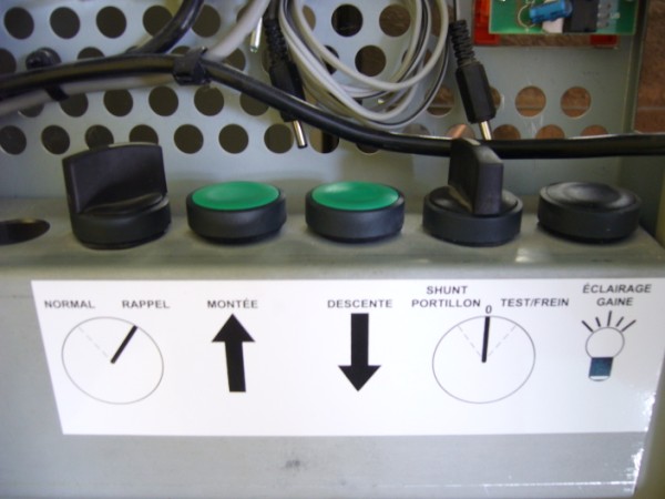
Image 7 ![]()
A close-up of the buttons in the hall maintenance/rescue panel...
'Rappel' is French for 'Inspection'
Image provided by: Jonathan Fitzpatrick
Ascenseurs et Automatismes de Gascognes
I know more!

Image 8 ![]()
Door operator and clutch...
Please note - both doors have a gate contact...
I wonder if that is a door restrictor device just to the left of the door motor drive assembly?
Image provided by: Jonathan Fitzpatrick
Ascenseurs et Automatismes de Gascognes
I know more!
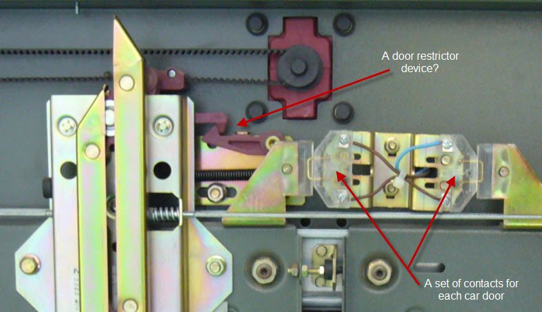
Image 8A
A close-up of the car door clutch assembly...
Hans van Lunsen informs me that the hook is used to keep
the cam and doors fully closed between landings...thanks Hans!
Image provided by: Jonathan Fitzpatrick
Ascenseurs et Automatismes de Gascognes
I know more!
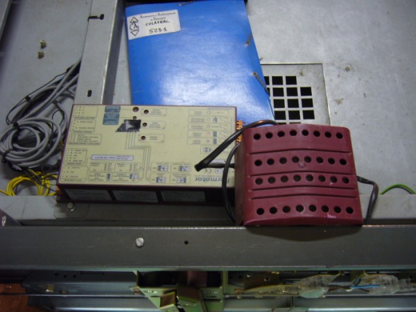
Image 9 ![]()
Door operator motor and controller...
Image provided by: Jonathan Fitzpatrick
Ascenseurs et Automatismes de Gascognes
I know more!
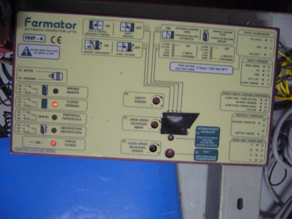
Image10 ![]()
We see it is a Fermator door operator...
Image provided by: Jonathan Fitzpatrick
Ascenseurs et Automatismes de Gascognes
I know more!
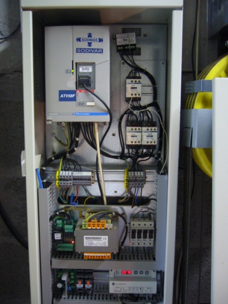
Image 11 ![]()
Part of the controller in the hoistway enclosure...
Image provided by: Jonathan Fitzpatrick
Ascenseurs et Automatismes de Gascognes
I know more!
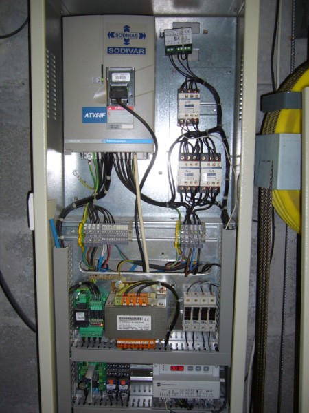
Image 12 ![]()
Part of the controller in the hoistway enclosure...
Image provided by: Jonathan Fitzpatrick
Ascenseurs et Automatismes de Gascognes
I know more!
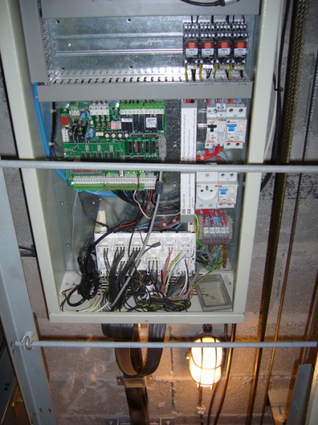
Image 13 ![]()
Part of the controller in the hoistway enclosure
and also the traveling cable junction box...
Image provided by: Jonathan Fitzpatrick
Ascenseurs et Automatismes de Gascognes
I know more!
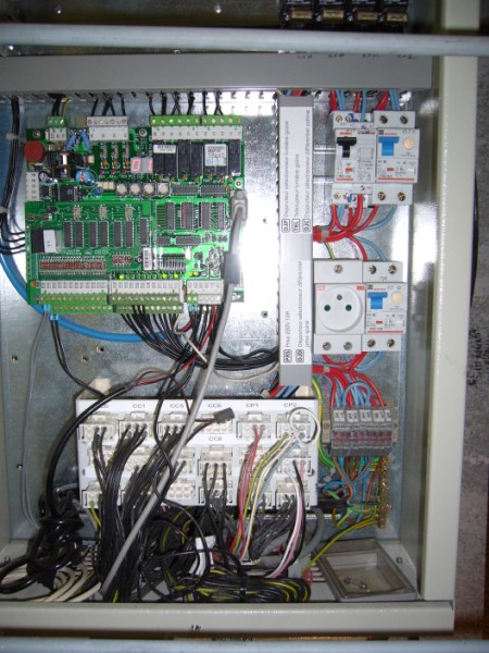
Image 14 ![]()
Another view of the traveling cable terminal block and
the circuit board that controls most of the elevator functions.
Hans van Lunsen informs me that this is a MEA F17 controller...thanks Hans!
Image provided by: Jonathan Fitzpatrick
Ascenseurs et Automatismes de Gascognes
I know more!
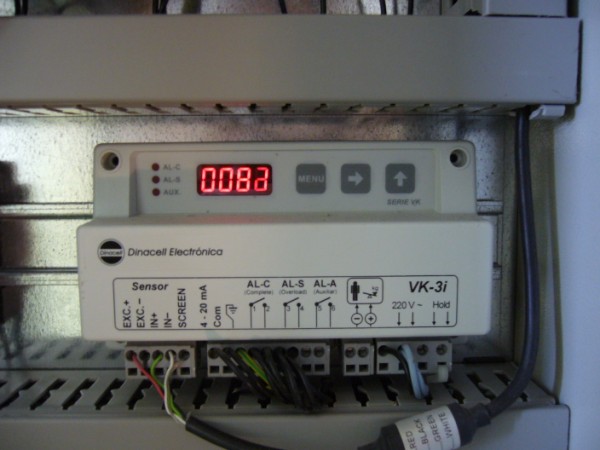
Image 15 ![]()
This is the load weighing device with Jonathan standing on the car...
Image provided by: Jonathan Fitzpatrick
Ascenseurs et Automatismes de Gascognes
I know more!
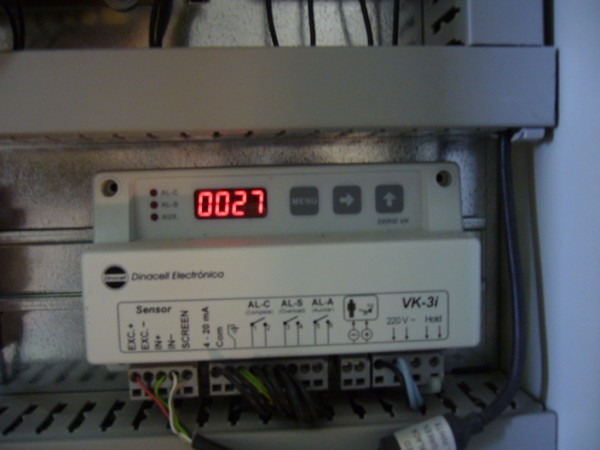
Image 16 ![]()
Jonathan's weight has been removed from the car...
Image provided by: Jonathan Fitzpatrick
Ascenseurs et Automatismes de Gascognes
I know more!
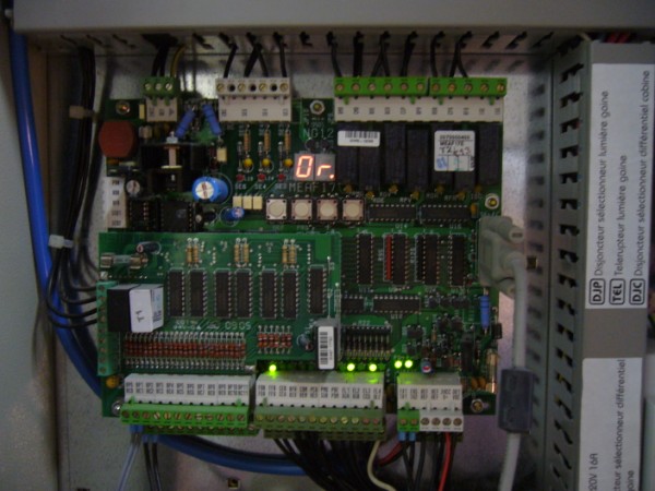
Image 17 ![]()
A close-up of the main circuit board...
Image provided by: Jonathan Fitzpatrick
Ascenseurs et Automatismes de Gascognes
I know more!
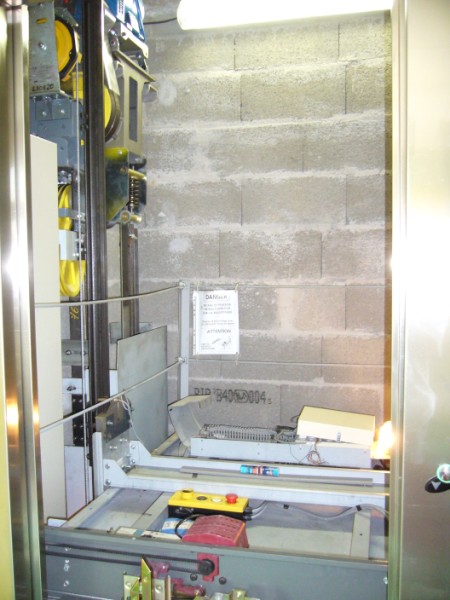
Image 18 ![]()
Welcome to the machine room!
Pretty much the heart of the operation right here...
Image provided by: Jonathan Fitzpatrick
Ascenseurs et Automatismes de Gascognes
I know more!
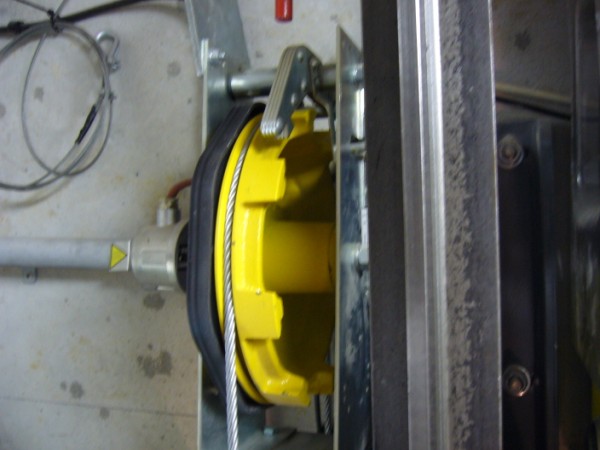
Image 19 ![]()
The governor...
Image provided by: Jonathan Fitzpatrick
Ascenseurs et Automatismes de Gascognes
I know more!
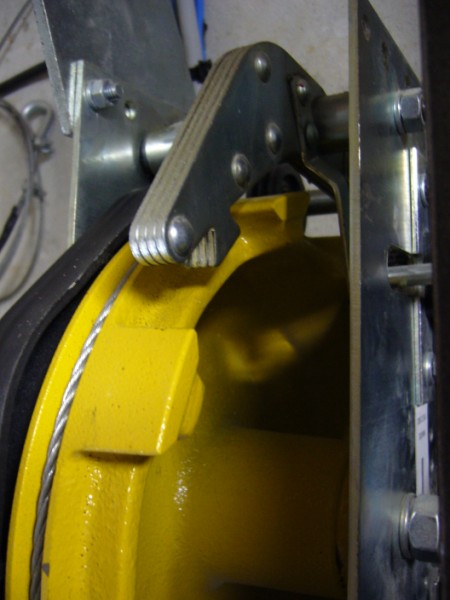
Image 20 ![]()
A close-up of the governor tripping pawl...
As you can see it is designed to work in both directions.
Image provided by: Jonathan Fitzpatrick
Ascenseurs et Automatismes de Gascognes
I know more!
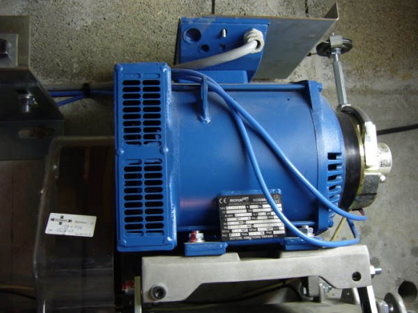
Image 21 ![]()
The device to the right of the motor is used to pick the brake during a rescue or maintenance.
It is controlled by the device with the red handle in the maintenance/rescue panel.
Image provided by: Jonathan Fitzpatrick
Ascenseurs et Automatismes de Gascognes
I know more!
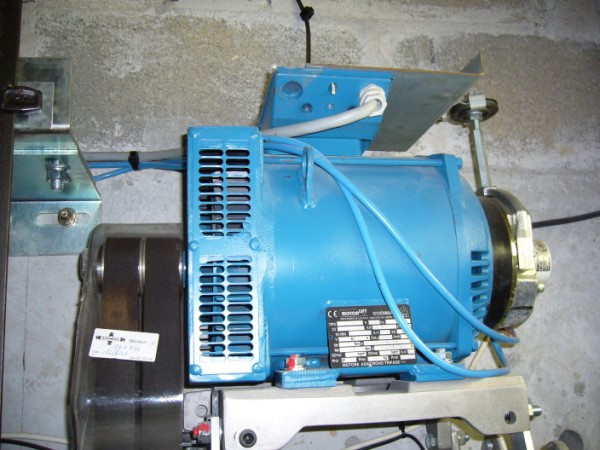
Image 22 ![]()
Drive belts - the newer version has a device that monitors the integrity of the belts.
Image provided by: Jonathan Fitzpatrick
Ascenseurs et Automatismes de Gascognes
I know more!
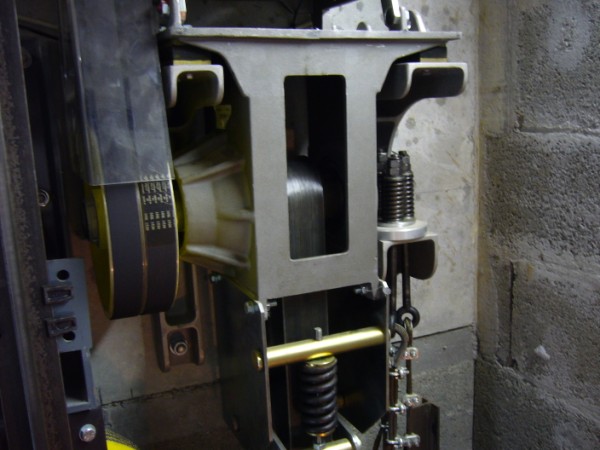
Image 23 ![]()
Part of the driving mechanism (speed reduction unit)...
Image provided by: Jonathan Fitzpatrick
Ascenseurs et Automatismes de Gascognes
I know more!
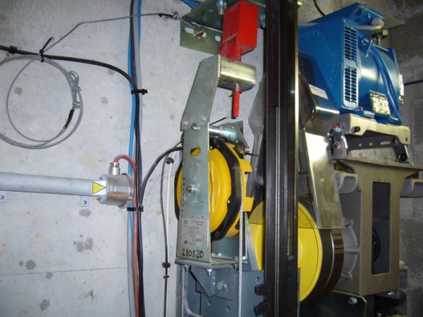
Image 24 ![]()
Most of the wiring appears to be installed without the use of protective conduit.
We allow this in the United States but only with very low voltages.
(30 volts rms or less or 42 volts dc or less - See NEC - 2008 - 620.21(A)(1)(c))
Image provided by: Jonathan Fitzpatrick
Ascenseurs et Automatismes de Gascognes
I know more!
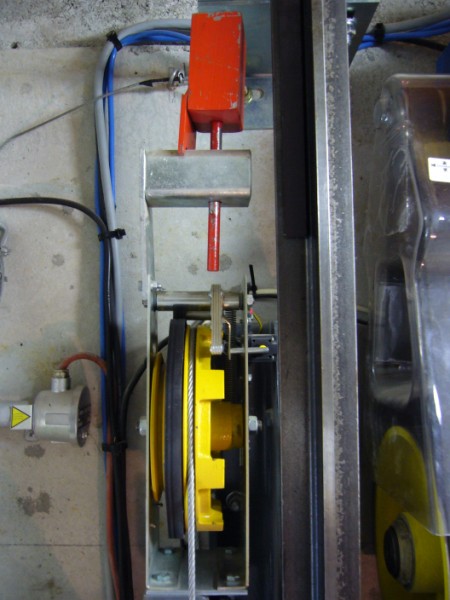
Image 25 ![]()
The red device over the governor is a small weight used to remotely and
manually set the operating pawl on the governor to test the car safeties.
Image provided by: Jonathan Fitzpatrick
Ascenseurs et Automatismes de Gascognes
I know more!
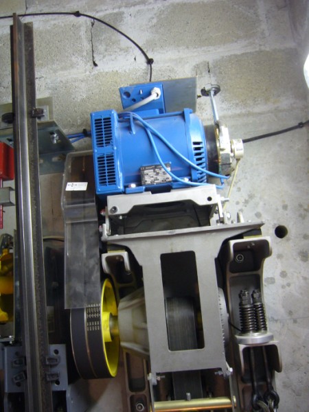
Image 26 ![]()
One of the dead-end hitch plates for the suspension ropes...
Image provided by: Jonathan Fitzpatrick
Ascenseurs et Automatismes de Gascognes
I know more!
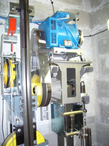
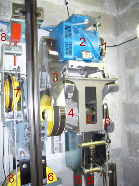
Image 27 ![]()
1 - Machine brake
2 - AC drive motor
3 - Drive belts
4 - Speed reduction unit
5 - Drive belt between speed reduction unit and counterweight
6 - Suspension ropes
7 - Governor
8 - Device to trigger the governor
Image provided by: Jonathan Fitzpatrick
Ascenseurs et Automatismes de Gascognes
I know more!
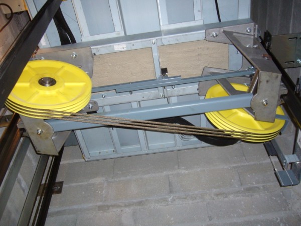
Image 28 ![]()
The 2:1 sheaves under the car...
The two bars and the switch (safety operated switch) are a part of the safety (parachute) device.
The safety sets instantaneously in the down direction but is progressive in the up direction.
Image provided by: Jonathan Fitzpatrick
Ascenseurs et Automatismes de Gascognes
I know more!
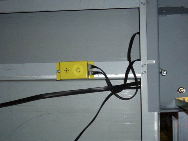
Image 29 ![]()
If a mechanic is stuck in the pit he/she would use this device to summons help...
Image provided by: Jonathan Fitzpatrick
Ascenseurs et Automatismes de Gascognes
I know more!
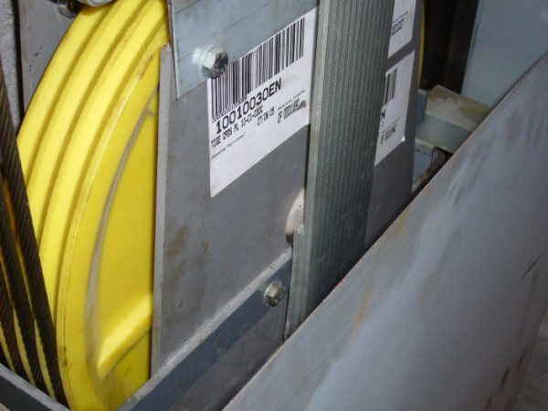
Image 30 ![]()
The counterweight sheave and the drive belt from the speed reduction unit...
Image provided by: Jonathan Fitzpatrick
Ascenseurs et Automatismes de Gascognes
I know more!
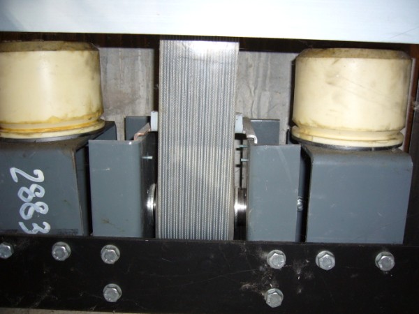
Image 31 ![]()
The counterweight buffers and the sheave for the drive belt in the pit
Image provided by: Jonathan Fitzpatrick
Ascenseurs et Automatismes de Gascognes
I know more!
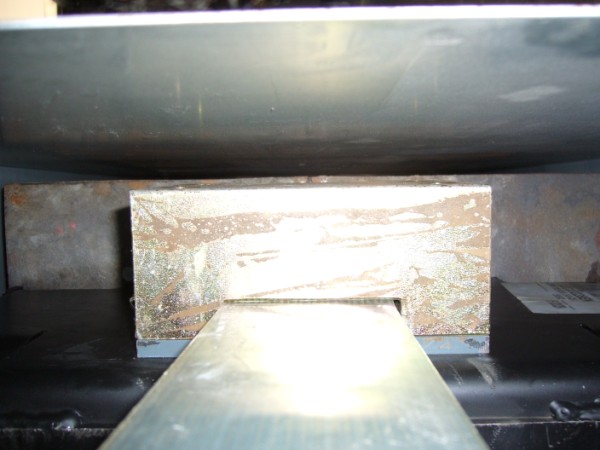
Image 32 ![]()
This is the point on the counterweight where the drive belt is attached...
Image provided by: Jonathan Fitzpatrick
Ascenseurs et Automatismes de Gascognes
I know more!
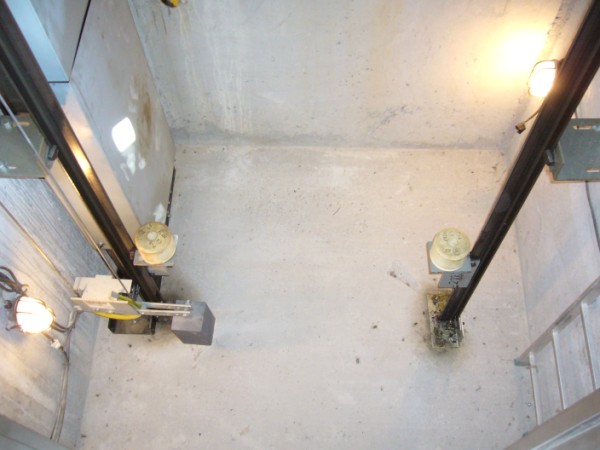
Image 33 ![]()
The pit...neat, clean and to the point!
Image provided by: Jonathan Fitzpatrick
Ascenseurs et Automatismes de Gascognes
I know more!
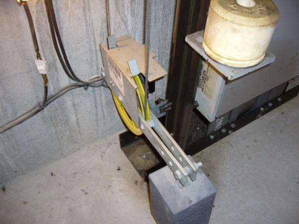
Image 34 ![]()
The governor rope tension sheave and the loss-of-tension switch...
One of the car buffers is also visible as is the counterweight guard.
Image provided by: Jonathan Fitzpatrick
Ascenseurs et Automatismes de Gascognes
I know more!

Image 35 ![]()
Another view of the governor rope tension sheave and switch...
Image provided by: Jonathan Fitzpatrick
Ascenseurs et Automatismes de Gascognes
I know more!
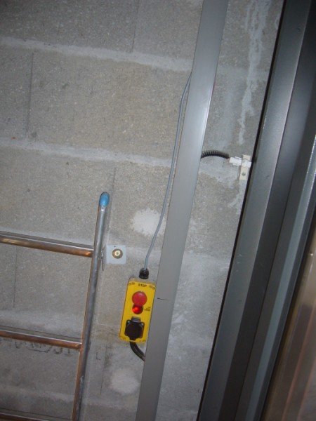
Image 36 ![]()
The pit ladder, stop switch and 220 volts AC receptacle...
Image provided by: Jonathan Fitzpatrick
Ascenseurs et Automatismes de Gascognes
I know more!
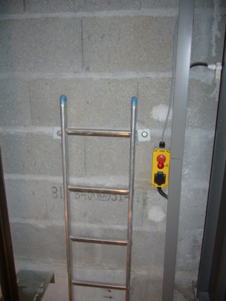
Image 37 ![]()
A close-up of the ladder...
Image provided by: Jonathan Fitzpatrick
Ascenseurs et Automatismes de Gascognes
I know more!
 E-mail me a link, image, suggestion, or comment!
Bob Desnoyers Elevator & Escalator Inspections, Inc.
Vertical Transportation Consultants & Inspectors
Vertical Transportation Authorities Having Jurisdiction
State of California - Conveyance - Authority Having Jurisdiction Site Map
Return to elevatorbob's Elevator Pictures
Advertise on One Stop Elevator
