
Antique Conveyances - Elevators
Microdrive Machines
Return to elevatorbob's Antique Conveyances
Return to elevatorbob's Electric Elevators
Return to elevatorbob's Elevator Pictures
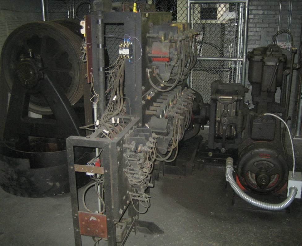
Image 1 ![]() (1 of 3)
(1 of 3)
The majority of the driving machines, brakes, gear boxes, and controller can be seen here.
The guards for the rotating brake have been removed and are on the floor next to the drive sheave.
This arrangement is similar in design to Drawing 3
Image provided by: Cole Haston
I know more!
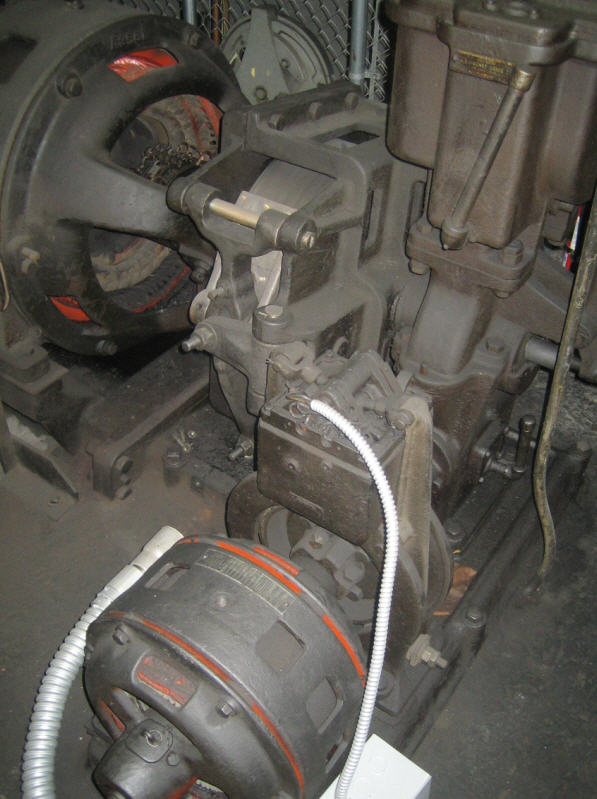
Image 2 ![]() (2 of 3)
(2 of 3)
A view of the main machine motor, the smaller auxiliary machine motor as well as both brake assemblies.
As you will see in Image 4 the main machine might also be gearless.
These motors appear to be of the AC type, however, the main machine seems
to have either a commutator or slip rings on the rotating element.
Both brake assemblies are of the AC type and the coils are submerged in oil.
Image provided by: Cole Haston
I know more!
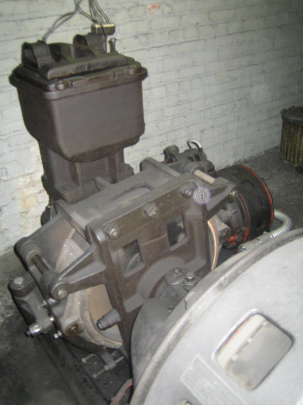
Image 3 ![]() (3 of 3)
(3 of 3)
A close-up of the "widow maker!"
Image provided by: Cole Haston
I know more!
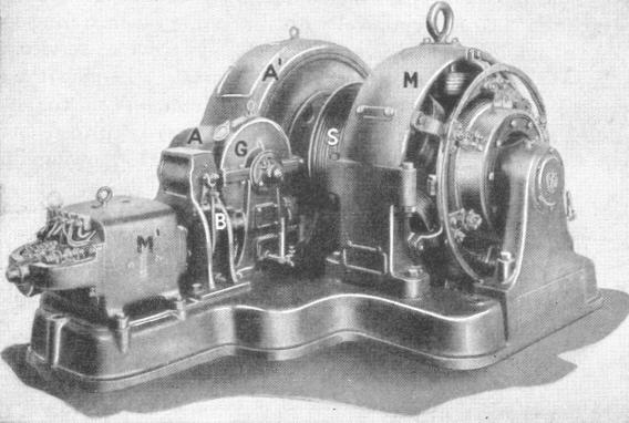
Image 4
The main machine might also be gearless...
This image was "borrowed" from the excellent book ELEVATORS
by Frederick A. Annett which can be purchased at elevatorbooks.com.
I know more!
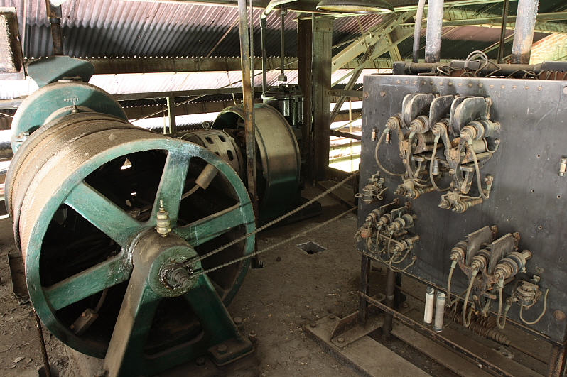
Image 5
Or the machine might be geared with a winding-drum...
Tennessee Coal & Iron's Ensley Works - Birmingham, Alabama, U.S.A.
(We think this is a microdrive unit...it sure looks like it.)
I would guess that the chain running from the drum shaft to the controller is used to
operate the "machine final limits" as required by most codes. (See A17.1S-2005 - 2.25.3.3.2)
Image provided by: Herbie T. Mann
I know more!
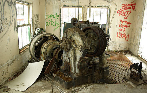
Image 6 ![]()
American Canning Company in Simcoe, Ontario, Canada
Another one...
Image provided by: Clark Monsieur
I know more!
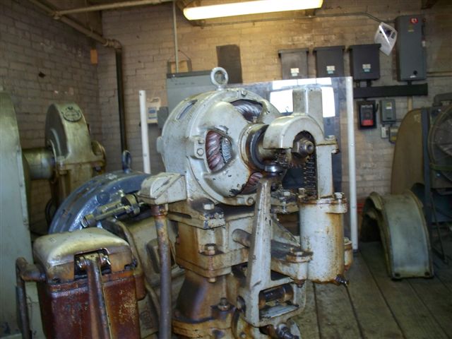
Image 7 (1 of 12)
The John Deere Plant in Horicon, Wisconsin, U.S.A.
Image provided by: Chad Weinberger & Albert Pritchard
I know more!
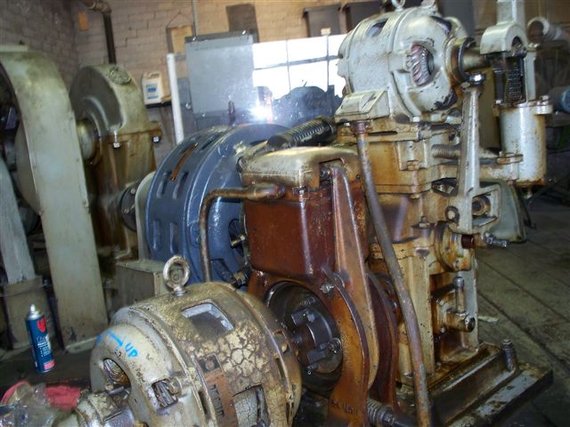
Image 8 (2 of 12)
The John Deere Plant in Horicon, Wisconsin, U.S.A.
Image provided by: Chad Weinberger & Albert Pritchard
I know more!
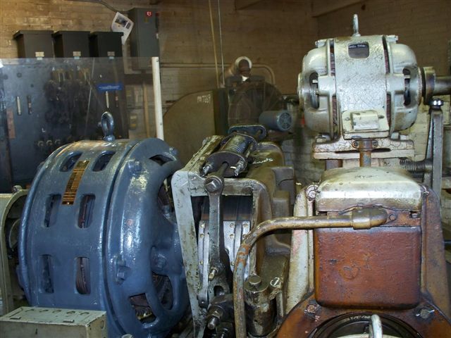
Image 9 (3 of 12)
The John Deere Plant in Horicon, Wisconsin, U.S.A.
Image provided by: Chad Weinberger & Albert Pritchard
I know more!
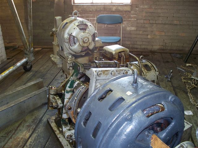
Image 10 (4 of 12)
The John Deere Plant in Horicon, Wisconsin, U.S.A.
Image provided by: Chad Weinberger & Albert Pritchard
I know more!
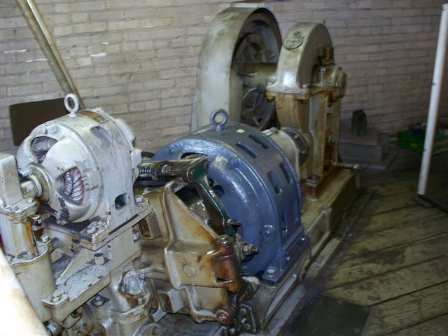
Image 11 (5 of 12)
The John Deere Plant in Horicon, Wisconsin, U.S.A.
Image provided by: Chad Weinberger & Albert Pritchard
I know more!
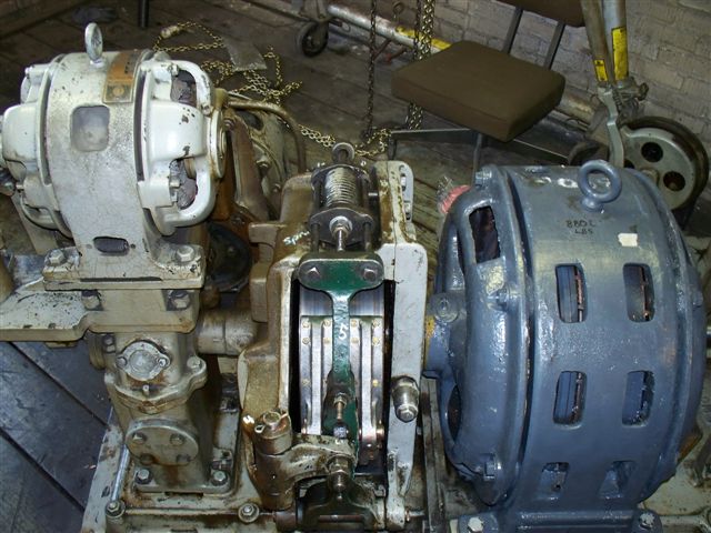
Image 12 (6 of 12)
The John Deere Plant in Horicon, Wisconsin, U.S.A.
Image provided by: Chad Weinberger & Albert Pritchard
I know more!
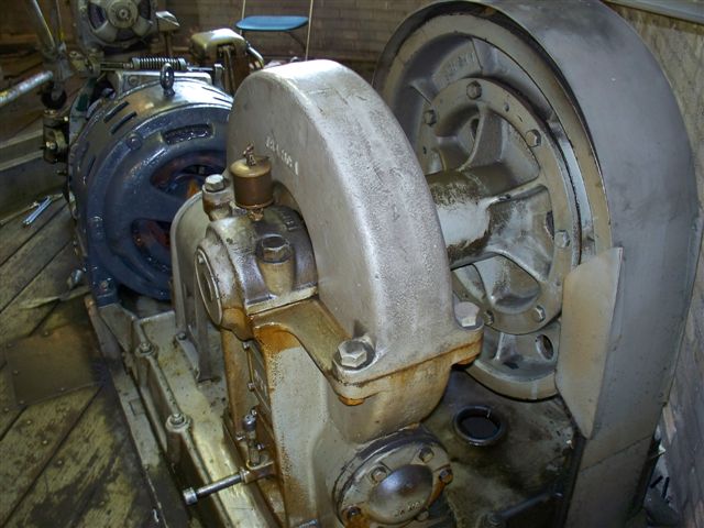
Image 13 (7 of 12)
The John Deere Plant in Horicon, Wisconsin, U.S.A.
Image provided by: Chad Weinberger & Albert Pritchard
I know more!
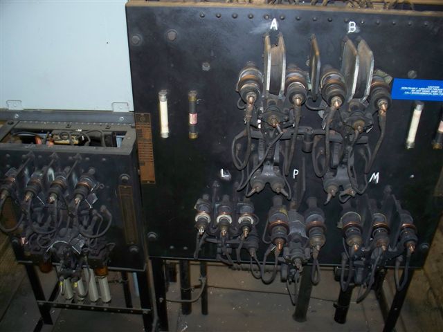
Image 14 (8 of 12)
The John Deere Plant in Horicon, Wisconsin, U.S.A.
Image provided by: Chad Weinberger & Albert Pritchard
I know more!
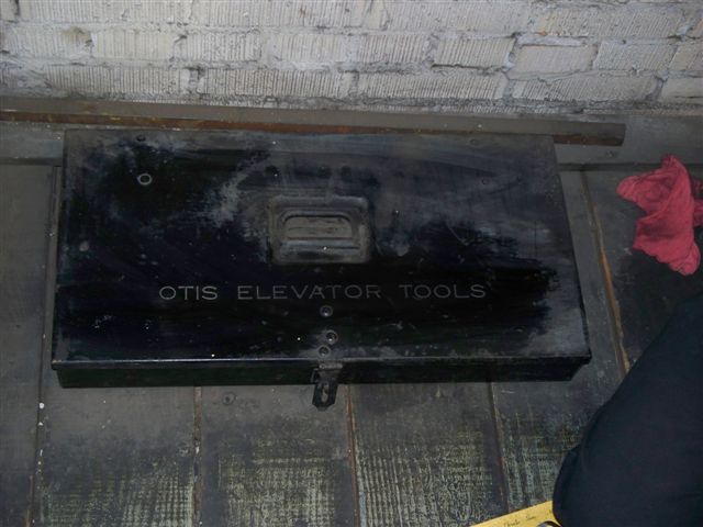
Image 15 (9 of 12)
What could be in here?
The John Deere Plant in Horicon, Wisconsin, U.S.A.
Image provided by: Chad Weinberger & Albert Pritchard
I know more!
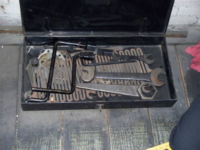
Image 16 (10 of 12)
Tools and what appear to be "resistors grids?"
The John Deere Plant in Horicon, Wisconsin, U.S.A.
Image provided by: Chad Weinberger & Albert Pritchard
I know more!
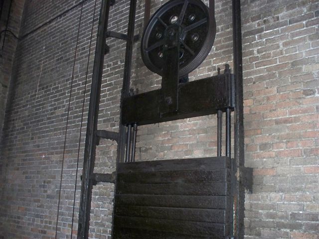
Image 17 (11 of 12)
The John Deere Plant in Horicon, Wisconsin, U.S.A.
Image provided by: Chad Weinberger & Albert Pritchard
I know more!
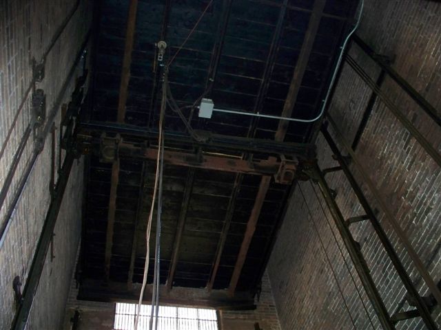
Image 18 (12 of 12)
The John Deere Plant in Horicon, Wisconsin, U.S.A.
Image provided by: Chad Weinberger & Albert Pritchard
I know more!
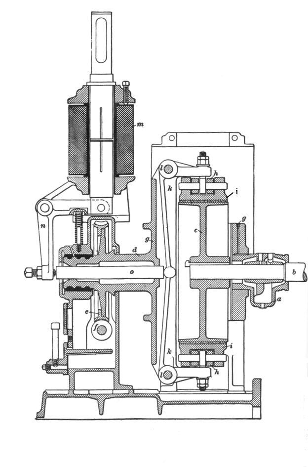
Drawing 1
This is a vertical section through the auxiliary machine and rotating brake.
Drawings 1 and 2 will be used to explain the operation of the rotating brake.
This drawing was "borrowed" from the excellent book ELECTRIC ELEVATORS
by Fred Hymans which can be purchased at elevatorbooks.com.
I know more!
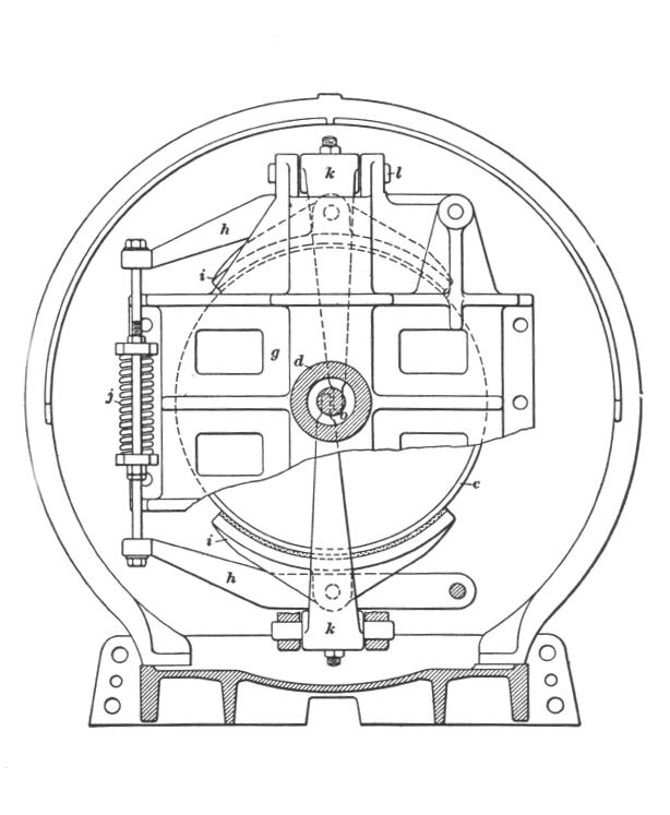
Drawing 2
Spring j is used to adjust the brake shoe i tension against the brake pulley c .
This drawing was "borrowed" from the excellent book ELECTRIC ELEVATORS
by Fred Hymans which can be purchased at elevatorbooks.com.
I know more!
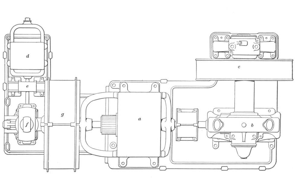
Drawing 3
This drawing was "borrowed" from the excellent book ELECTRIC ELEVATORS
by Fred Hymans which can be purchased at elevatorbooks.com.
I know more!
![]()
![]()
![]()
 E-mail me a link, image, suggestion, or comment!
Bob Desnoyers Elevator & Escalator Inspections, Inc.
Vertical Transportation Consultants & Inspectors
Vertical Transportation Authorities Having Jurisdiction
State of California - Conveyance - Authority Having Jurisdiction Site Map
Return to elevatorbob's Elevator Pictures
Advertise on One Stop Elevator
